Cooper Gfci Wiring Diagram
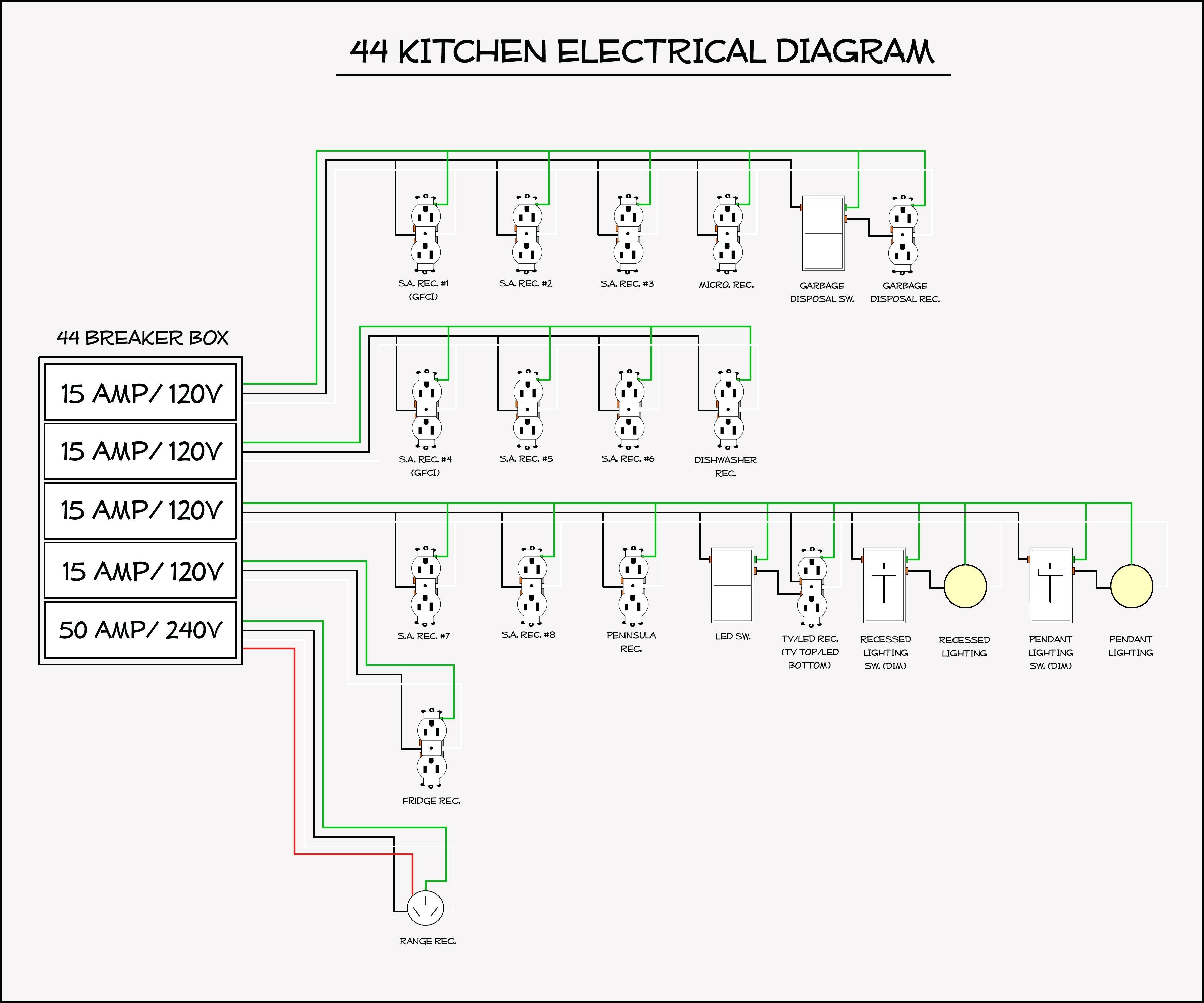
Safety ul listed, fully compliant with all latest ul 943 (4th edition) class a gfci, ul 498 hospital grade requirements. In this gfci outlet wiring and installation diagram, the combo (switch + outlet), spst (single way) switch and ordinary outlet is connected to the load side of gfci.
18 Popular Cooper Gfci Wiring Diagram Solutions Tone Tastic

In this gfci outlet wiring and installation diagram the combo switch outlet spst single way switch and ordinary outlet is connected to the load side of gfci.

Cooper gfci wiring diagram. Effectively read a wiring diagram one provides to find out how the components inside the system operate. Pool light gfci wiring diagram black white green red. The hot source is spliced to the line terminal on the receptacle and to one terminal on the light switch.
• understand basic wiring principles and techniques • can interpret wiring diagrams • have circuit wiring experience • are prepared to take a few minutes to test your work, making sure that you have wired the gfci receptacle correctly. Protected receptacle (s) will be connected to the gfci load side as shown below. How to wire cooper 277 pilot light switch wire switch home electrical wiring house wiring.
Test the gfci by pressing the black “test” button on the outlet. Gfci, back & side wire 20 125 a, b, bk, gy, la,. I've installed a gfci switch / receptacle combo and believe its wired correctly but have pulled the fuse until i get some verification.
From electrical switches and receptacles, to gfci outlets and usb chargers, pass & seymour electrical wiring devices, connectors and outlets are. We are guided by our commitment to do business right, to operate sustainably and to help our customers manage power ─ today and well into the future. Wire double rocker switch to gfci wire switch home electrical wiring house wiring.
2020 wiring diagram by anna r. Hospital grade modular gfci back & side wire. Ground connection is not shown.
• button:for installation in wet locations, protect the gfci receptacle with green wire Leviton gfci outlets are engineered to help protect people from the hazards of electric shock and electrocution. Power is connected to the gfci line side.
Injunction of 2 wires is generally indicated by black dot in the intersection of two lines. Eaton gfci outlet wiring diagram. The switch box had 3 pairs or wire attached to the orginal switch 3 white 3 black.
• do not install this gfci receptacle on a circuit that powers life support equipment because if the gfci trips it will shut down the equipment. The neutral and ground wires are spliced together and run to each device in the circuit. Cooper 3 way switch wiring diagram.
Load a cable consists of 2 or 3 wires. Wiring devices & connectivity eaton is an intelligent power management company dedicated to improving the quality of life and protecting the environment for people everywhere. The following wiring shows an ordinary outlet has been wired and protected through a double pole gfci circuit breaker.
Replace the receptacle, screw it back into the box, and attach the cover plate. Cooper wiring device gfci receptacles. *line and load terminal locations can differ between gfci receptacle brands.
Wiring a two poles gfci circuit breaker. Technical data effective november 2014 electrical sector 203 cooper circle peachtree city, ga 30269 united states eaton.com cooperwiringdevices.com electrical sector canada operations Eaton commercial grade 20 amp straight blade single receptacle with side wiring white 1876w box the home depot straight blade eaton receptacles use this gfci receptacle with copper or.
It means, all the connected loads to the load terminals of gfci are protected. Wiring cooper gfci switch / receptacle combo. Trsgf20 line art with dimensions.
The toggle switch in the combo switch outlet controls the first light bulb while the single way. This diagram illustrates wiring a gfci receptacle and light switch in the same outlet box a common arrangement in a bathroom with limited space. Wiring diagram not just provides comprehensive illustrations of what you can do, but additionally the methods you ought to adhere to although doing so.
Wiring a gfci receptacle is a little more complicated than hooking up a regular outlet but easily learned once explained. ( see diagram a ). This diagram illustrates wiring a gfci receptacle and light switch in the same outlet box, a common arrangement in a bathroom with limited space.
Cooper wiring devices installation instructions cooper industries eaton wiring devices products gfci ground fault if the device is determined to no longer be able to safely provide protected power. Do not use it with aluminum wire. Sometimes the cables will cross.
Our bathroom only has a single 2 prong outlet as part of the light fixture. Single switch wiring diagram google search light switch wiring home electrical wiring installing a light switch. Plug a clock radio or light into the outlet.
Trsgf15 line art with dimensions figure 4. Connect the bare ground wire to the green (ground) screw. 3 way switch wiring diagram.
Delivers power from the service panel.
Cooper Gfci Outlet Wiring Diagram Wiring23
Cooper Gfci Wiring Diagram
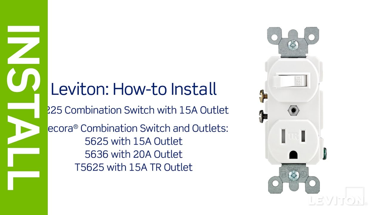
Leviton Switch Outlet Combination Wiring Diagram Free Wiring Diagram
5967 Cooper Gfci Schematic Wiring Diagram Word Download 399 PDF Format
Unique Cooper Gfci Wiring Diagram diagram diagramsample diagramtemplate wiringdiagram

Garbage Disposal Wiring Diagram Cadician's Blog
Cooper Gfci Outlet Wiring Diagram Popular Cooper Gfci Wiring Diagram Within Outlet, Wellread.Me

How To Wire, Way Switch Outlet Top Cooper Gfci Outlet Switch Wiring Diagram Glamorous Dimmer

Cooper Gfci Combination Switch Wiring Diagram Wiring Diagram

17 Luxury Leviton 5245 Wiring Diagram
Cooper Gfci Outlet Wiring Diagram Most Image Result, Electrical Outlet Wiring With Switch

21 New Cooper Gfci Outlet Switch Wiring Diagram
54 Cooper Gfci Outlet Wiring Diagram Wiring Diagram Harness

Cooper Gfci Outlet Wiring Diagram / Wiring A Gfci Outlet How To Wire Line And Load Schematics

49 Cooper Gfci Outlet Wiring Diagram Wiring Harness Diagram
Cooper Gfci Schematic Wiring Manual EBooks Gfci Wiring Diagram Wiring Diagram
How to install and troubleshoot GFCI

Cooper Gfci Outlet Wiring Diagram Wiring Diagram

Unique Cooper Gfci Wiring Diagram diagram diagramsample diagramtemplate wiringdiagram
