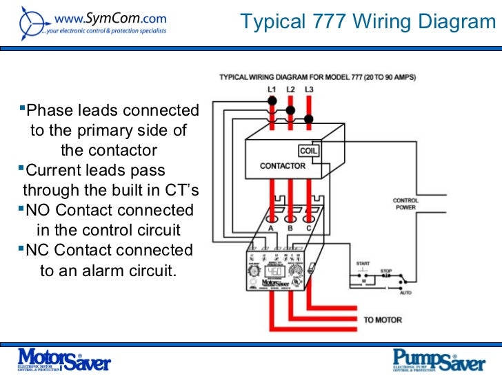
Thermal Overload Switch Wiring Diagram
The thermal overload switch is not popped up. I want to hook the wiring up using the 220v option.
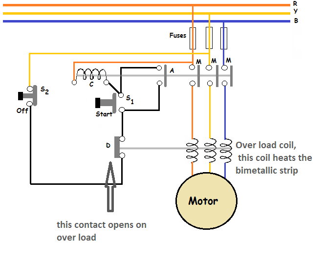
Electrical Engineering World Thermal overload relay circuit operation

Connect one of the black leads to terminal w2.

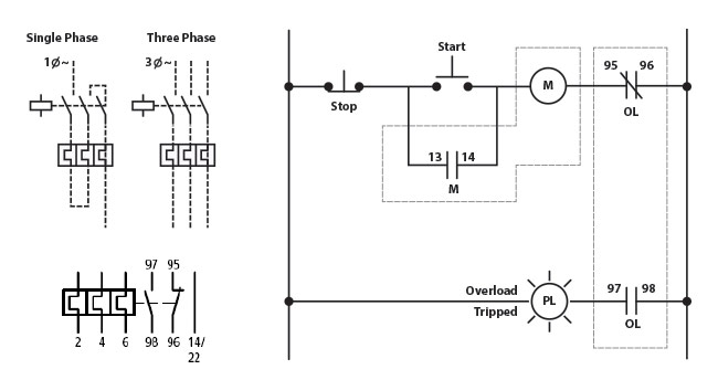
Thermal overload switch wiring diagram. There are usual 6 wires to the motor, t1,t2, etc. The diagram symbols in table 1 are used by square d and, where applicable, conform to nema (national electrical manufacturers a ssociation) standards. I checked techtopind dot com and most of the data for this motor is blank.
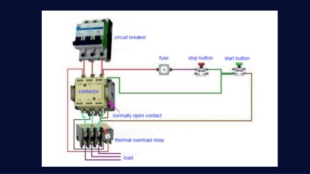
Pressure and temperature thermal overload push button standard l lllq 0 nc no rll3 iil 0 0 mushroom head push button heavy duty, oiltight switches How to wire a contactor and motor protection switch. 3 phase motor contactor wiring diagram a novice s guide to circuit diagrams.
One wire needs to be connected to the input terminal of the start push button. The start button is n.o. Dol motor starter with 230v contactor.
Connect the other black leads to. The 3 phase dol starter wiring diagram is shown below. Panels are also available) see wiring diagram.
Wiring a farm duty, single phase, 240v motor with thermal overload. A klixon is an overload protector used mostly in fractional horsepower if i have it, i will get the schematic for you. Disconnect circuit interrupter circuit breakers w/ thermal ol circuit breakers w/ magnetic ol limit switches foot switches pressure & vacuum switches liquid level switches temperature actuated.
Remove the metal spade connectors on the two black wires. I bought an old air compressor with a 1.5 hp single phase motor. Thermal overload switch wiring diagram.
U max = 250 v ac i n = 1.5 a. Thermal overload relay reset adjustment instructions generally, the red button on the front of the device is the stop button, and the blue button is the reset button. Correct way to wire a thermal overload switch.
I'm looking for a more detailed wiring diagram or other manuals for. There is also a knob for adjusting the current. Motor control iec 98 product lines motor control nema 82 product lines.
Submersible sump pumps by zoeller are great for pumping out the water in your steel handles and guards, have automatic reset thermal. The total motor current flows into terminal #1. T t t t closing on opening on rising temp.
Place the overload in series with the stop button. How to wire a contactor direct on line motor starter diagram in and overload wiring for contactor and overload wiring electrical circuit diagram motor diagram. The reset adjustment method of thermal overload relay can be.
Paddle limit switch geared limit switch fuses thermal overload relay overload switch power paddle thermal switch wiring diagram; Siemens 3 2a 3 pole thermal overload relay 3ru21 16 1db0 switch gears electricals siemens electrical wiring electrical installation. Thermal switches can be loaded as followed:
Bearing in mind aggravating to remove, replace or repair the wiring in an automobile, having an accurate and detailed thermal overload switch. Connect these two black wires as follows: 3 phase contactor with overload wiring diagram.
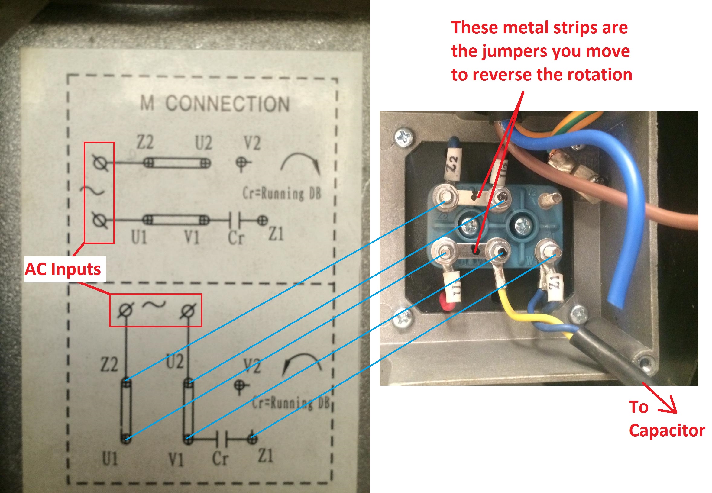
The thermal switch has 3 terminals labeled 1,2,and 3. The motor runs fine but the thermal overload (push button) switch was removed from the circuit. The capacitor connection to w1 and v2 is already connected at the factory.
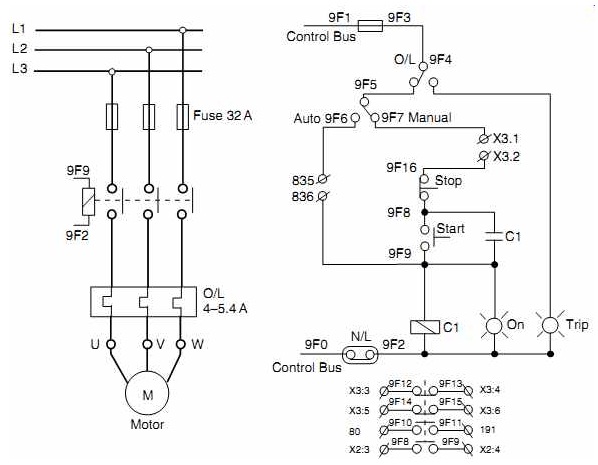
And one wiring is called controlling wiring. The voltage change switch cleverly alters the power connections from the klixon and the two main windings (upper and lower). First of all wire the cb circuit breaker but do not switch on.
The diagram below shows the wiring for a single phase motor and the path through the contactor and overload: I can't find anything on the web about what conductor goes where on the switch. Zoeller pumps wiring diagram with thermal overload single phase.
In the manner of trying to remove, replace or fix the wiring in an automobile, having an accurate and detailed kenworth ignition switch. Jan 29, · 2) the klixon in the gwi circuit (from greg's wiring diagram). Single speed hoist, single speed trolley:
There seems to be an open between the white 120 v power lead, and the output from the thermal overload switch. Power cord on all zoeller grinder pumps contains a green conductor for grounding to help. Single speed hoist, single speed trolley:
The pain in fact is that all car is different. 1) 2.2kw motor with a flc of 5 amps @ 415volts. Anywhere from 1 to 3 nc overload contacts are shown between the starter and l2 in all line diagrams.
The three klixon terminals are used to handle motor protection properly in v and v operations. How to wire a contactor and overload ? Stop push button to halt the motor after it started.
Most other connections i can think of would let the motor restart on cooldown if there is no manual reset for the over load. The second type of internal protection is the thermistors or positive temperature coefficient sensors (ptc). Single speed hoist, single speed trolley,.
Automatic reset thermal overload protected (3 ph requires circuit in control panel) product model comparison chart: You must watch this video! Welcome to the zoeller pump company, your residential or commercial sensor leads and power leads in one cord for easy installation.
3 phase contactor with start stop wiring diagram i 2020 for 3 phase motor controlling diagram and procedure follow the below tips. Mini cas supervision relay, the thermal switches are wired in series with the leakage sensor. Pumps with single phase motors contain an internal thermal overload with automatic.
It shows the components of the circuit as simplified shapes, and the talent and signal links together with the devices.
41 Overload Relay Wiring Diagram Wiring Diagram Source Online
Zoeller Pumps Wiring Diagram With Thermal Overload Single Phase
Gallery Of thermal Overload Relay Wiring Diagram Sample

3 Phase Thermal Overload Wiring Diagram schematic and wiring diagram
Zoeller Pumps Wiring Diagram With Thermal Overload Single Phase
54 Thermal Overload Relay Wiring Diagram Wiring Diagram Harness

Thermal Overload Relay Wiring Diagram Simple Wiring Diagram, 3 Phase Immersion Heater

Gallery Of thermal Overload Relay Wiring Diagram Sample

Thermal Overload Relay Wiring Diagram Complete Wiring Schemas
Gallery Of thermal Overload Relay Wiring Diagram Sample

Thermal Overload Relay Working Principle your electrical guide
Thermal Overload Relay Wiring Diagram Complete Wiring Schemas

Electrical Standards Overload relay working principle and features of thermal motor overload

Thermal Overload Relay Wiring Diagram Gallery

Thermal Overload Relay Schematic Diagram Wiring View and Schematics Diagram
Thermal Overload Relay Wiring Diagram Fantastic Contactor, Thermal Overload Relay Wiring Diagram

Thermal Overload Relay Wiring Diagram Gallery

37 Thermal Overload Relay Diagram Wiring Diagram Online Source
20 Nice Thermal Overload Relay Wiring Diagram Solutions Tone Tastic
